The oscillation frequency of a bar resting on two rollers turning
towards each other is the square root of the coefficient of
kinetic friction times twice acceleration of gravity (9.8 m/s^2)
divided by the horizontal distance between the two rollers:
⍵ = √ (2 * uK * g / L)
This paper shows how the formula is computed, by summing forces
and torques. There is data from tests and measurements of
oscillation frequency using five different bars at varying wheel
base lengths, that prove the formula is correct.
There are qualitative and quantitative proofs of this formula,
recorded demonstrations, and data from empirical tests. There is
background information about sources of information and where to
find more information. There are explanations and videos about how
to construct the test fixture, pictured below, used to model the
problem.
The conclusion is that this formula is correct, accurate, and
provable with a strong statistical correlation between wheel base
and oscillation rate.
How to
compute oscillation frequency of the bar
There are five steps to computing oscillation frequency of the
bar:
1. Sum vertical
forces
2. Sum horizontal forces
3. Sum torques
4. Compute acceleration
5. Write equation of motion
It would be important to note that oscillation frequency of
the bar is computed, and that forces and torques on the
bar are summed.
Sum vertical
forces on the bar
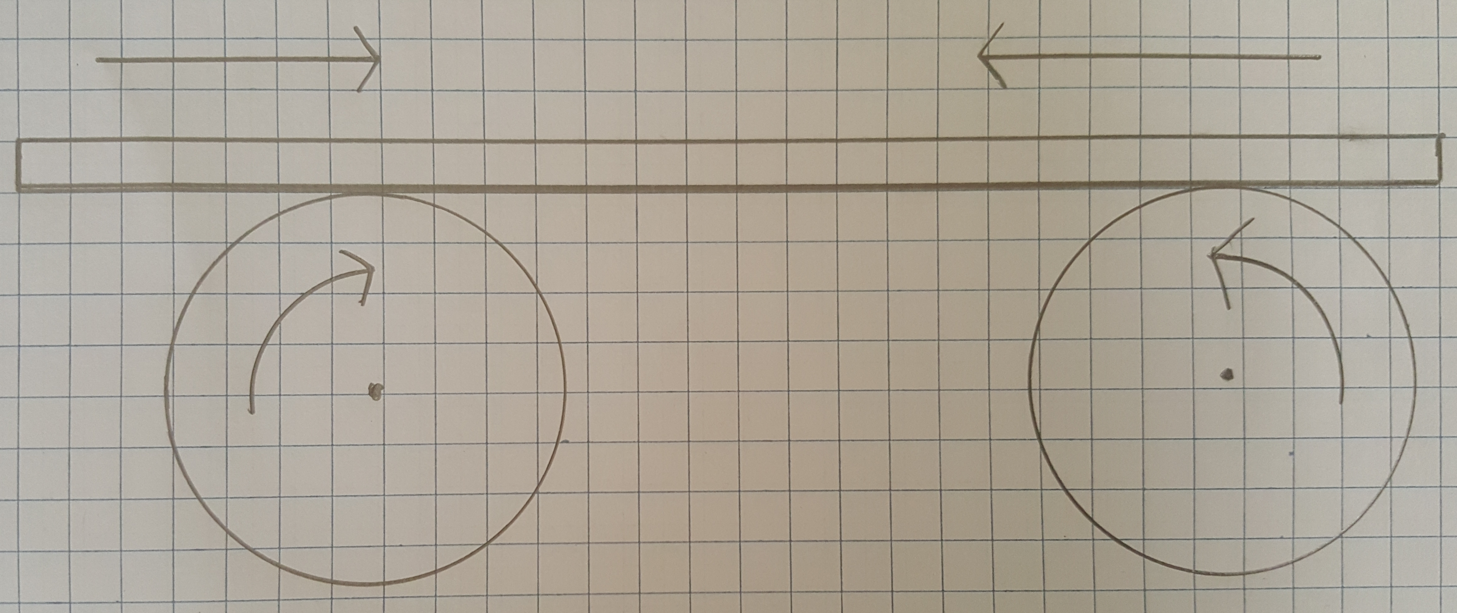
There are two vertical forces in effect:
Normal forces, from the two rotors
supporting the par, pointing up, in the positive Y
direction, and
Gravity pulling the bar down, in the
negative Y direction.
The bar is not moving up or down so the vertical forces sum to
zero. The expressions are:
Nl + Nr - mg = 0
Nl + Nr =mg
The two normal forces are constantly changing. They are not equal.
The bar is continuously moving back and forth and at almost any
time more of the bar sits over one roller. This would mean the
normal force of that rotor supporting more of the bar would be
greater than the other rotor.
While the two normal forces are rarely equal and continuously
changing, they sum to mass times gravity at all times.
Sum horizontal
forces on the bar
The only horizontal forces in effect are friction.
Friction pointing to the left. Negative horizontal direction.
When the bar is moving to the right, or in the positive X
direction, it is driven by the rotor on the left. There is
friction from the rotor on the right, opposing that motion.
Friction opposes motion. The rotor on the right is opposing motion
to the right, creating friction that points to the left, or in the
negative X direction. The direction of friction is to the left,
and it originates from the rotor on the right. The force is in the
negative X direction.
Friction is equal to the coefficient of kinetic friction times the
normal force. The expression for this is -uK*Nr
This friction is kinetic friction because the rotor on the right
is sliding against the bar when the bar moves to the right.
Friction pointing to the right. Positive horizontal direction
When the bar is moving to the left, or in the negative X
direction, it is driven by the rotor on the right. There is
friction from the rotor on the left, opposing motion to the left.
Friction opposes motion. The rotor on the left is opposing the
motion to the left, creating friction that points to the right, or
in the positive X direction. The direction of friction is to the
right. It originates from the rotor on the left. The force of
friction is in the positive X direction.
Friction is equal to the coefficient of kinetic friction times the
normal force. The expression for this force is +uK*Nl
Sum of horizontal forces on the bar
The bar is moving nearly all the time. It is speeding up, slowing
down, and changing direction. It is accelerating. The horizontal
forces sum to mass times acceleration because the bar is moving
horizontally:
uK * Nl - uK * Nr = ma
Nl - Nr = ma/uK
Sum torques on the bar
There are four issues to consider when evaluating torques in a
system:
Axis of rotation
Lever arm length
Magnitude of force on lever arm
Direction of force relative to lever
arm
If there is a torque then there is an axis around which the object
is moving or ‘wants’ to move because of the force on it. The best
example of this is a person pushing a door on a hinge to close it.
In this example the door hinge is the axis of rotation. The
distance between door hinge and the person pushing the door is the
length of the lever arm. The sine of the angle between the
direction of force and plane of the lever is multiplied by
magnitude of the force and length of the lever arm. The result of
such an expression is the torque.
Once an axis has been decided on, all torques in the system must
be evaluated as revolving, or attempting to revolve, around that
single axis.
Six torques on the bar, in three pairs
Torques imposed by the normal forces on
the bar
Torques imposed by the force of
friction
Torques imposed by gravity
The torques imposed by normal forces on the bar are used, with the
horizontal and vertical force summations, to isolate acceleration.
The two other force pairs exist but are not used to compute
oscillation frequency. All torques are presented because sources
more reliable than this paper also tally up all torques.
Axis of rotation is the bar center of mass
A single axis of rotation must be identified in order to compute
torques. There are several strategies for doing this. In this
paper symmetry is used because it is generally a good approach in
mechanical physics, electricity, and magnetism.
The center of mass of the bar is designated as the axis of
rotation. The bar is assumed to have uniform linear mass density
and therefore the center of mass is the linear center of the bar.
Locate the center of mass
The problem with choosing this axis of rotation is that the bar is
constantly moving back and forth. In order to compute a torque the
length of the arm and location of the axis must be correctly
identified mathematically. This is accomplished by choosing the Y
axis to intersect the middle of the wheel base, and using a
variable “x” to represent how far the center of mass is from the Y
axis.
If the center of mass is left of the Y axis, then x is a negative
number. If the center of mass has oscillated to the right of the Y
axis, then X is a positive number. The location of the axis can
now be represented as being at location L/2 + x, where L is the
length of the wheel base, L/2 is the middle of the wheel base, and
x is distance between center of mass and center of wheel base. x
is positive if the center of mass sits to the right of the Y axis,
and x is a negative number of center of mass sits to the left.
Torques from normal force on the bar
There are two torques from normal forces on the bar. There is a
clock-wise torque from the normal force of the left rotor, and a
counter-clockwise torque normal force of the right rotor.
Clockwise torque from normal force of left rotor
If the axis of rotation is the bar center of mass, then the normal
force from the left rotor is attempting to both push the bar up,
and to rotate it in a clockwise direction. With torques, clockwise
is a negative direction. This torque is represented as the normal
force times the lever-arm length of L/2 - x. Choosing +x or -x is
arbitrary but correct as long as the opposing torque uses L/2+x.
This convention means, correctly, that L, the length of the wheel
base, is L/2 - x + L/2 + x = 2 * L/2.
Torque = Force * Lever Arm Length * Sine of theta.
The length of the left lever arm is L/2 - x. The force is the left
normal force Nl. The angle between the direction of force and
lever arm is ninety degrees. The sine of ninety degrees is
one.
Torque from the left rotor is -Nl * (L/2 - x).
Counter-clockwise torque from normal force of right rotor
If the axis of rotation is the bar center of mass, then the normal
force from the right rotor is attempting to both push the bar up,
and rotate it in a counter-clockwise direction. With torques,
counter-clockwise is a positive direction. This torque is
represented as the normal force times the lever-arm length of L/2
+ x. Choosing +x or -x is arbitrary but correct as long as the
opposing torque uses L/2 - x.
The length of the right lever arm is L/2 - x. The force is the
right normal force Nr. The angle between the direction of force
and lever arm is ninety degrees. The sine of ninety degrees
is one.
Torque from the right rotor is +Nr * (L/2 + x).
These torques sum to zero. The bar is not rotating so the
expression for torques from the normal force is:
Nr * (L/2 + x) - Nl * (L/2 - x) = 0
While this is the only torque used to compute oscillation
frequency all professors and text books with explanations of this
problem enumerate all the torques.
Torques from friction sum to zero
Forces of friction drive the bar horizontally in the direction
opposing motion. The same force drives a torque attempting to
rotate the bar around the axis, which is the center of mass. The
direction of the frictional forces is towards the axis, meaning
the angle between direction of force and lever arm is zero. The
sine of zero is zero, so the torques in this case are zero because
Force * Arm length * sine of zero degrees is zero.
Torque on the bar from gravity
Torques from gravity sum to zero. To understand torques from
gravity in this system remember that the axis of rotation is the
linear center of the bar.
The bar to the left side of the axis is pulled down by gravity,
and if not obstructed by the roller would also pull the bar in a
counter-clockwise direction. This is a positive torque. Similar to
the formula used to sum torque from the normal forces, the torque
from gravity, on the left side of the bar, is mg * (L/2 - x). The
torque from gravity on the right side of the bar is mg * (L/2 +
x).
The bar is not rotating so the torques from gravity sum to zero.
The expression is:
mg(L/2 + x) - mg (L/2 - x) = 0
Explanatory note to those who disagree with this
interpretation.
Some experts, including the professor who taught this problem,
would disagree with the logic and principles used in this specific
computation. An argument can be made that gravity acts through the
center of mass of any object. The object in this case is a rod of
uniform linear density. The center of mass is the linear center.
While I agree with this interpretation, I view it as a valid
interpretation and not a technical fact. Gravity is operating
equally on all parts of the rod. For this reason choosing a lever
arm of any fixed length is flawed logic, but computing torques
requires a fixed length arm.
The alternative interpretation, assuming gravity operates
exclusively through the center of mass, which is the axis of
rotation, would mean the arm length is zero. In this case the sum
of torques from gravity is zero because length (zero) times angle
times force is zero.
Combine the equations. Isolate Nl, Nr, and acceleration
At this point there are written equations, summing vertical and
horizontal forces, and torques around the bar center of gravity
imposed by normal force. Respectively these equations are:
Vertical forces: Nl + Nr =mg
Horizontal forces: Nl - Nr = ma/uK
Torque from normal force: Nr * (L/2 + x) - Nl
* (L/2 - x) = 0
The next steps in this process is to isolate acceleration. This is
accomplished by rearranging the torques expression so that it has
Nl + Nr, and Nl - Nr in it. That allows mg and ma/uK to be
substituted in. When acceleration is in the equation it can be
isolated and equated with w^2*x (w represents omega, angular
frequency).
Steps to rearrange and substitute terms in the torques expression
are as follows:
The original expression for torque from normal force of the rotors
is:
Nr * (L/2 + x) - Nl * (L/2 - x) = 0
Multiply out all terms in the torques expression, giving:
Nr * L/2 + Nr * x - Nl * L/2
+ Nl * x = 0
Group terms with L/2 and x, giving:
L/2 * (Nr - Nl) + x * (Nl + Nr) = 0
The result now has Nl + Nr which can now be substituted for mg,
resulting in:
L/2(Nr - Nl) + mg*x = 0
The expression has Nr - Nl, and what is needed is Nl - Nr, so some
creative sign switching is in order. If the prefix term L/2 is
given a negative sign, then signs on terms inside the brackets can
be reversed. This preserves the value of the expression and
permits using Nl - Nr.
L/2(Nr-Nl) = -L/2(Nl-Nr)
Because this is true the full expression becomes:
-L/2(Nl - Nr) + mg*x = 0
Now Nl - Nr can be substituted for ma/uK, giving:
-L/2 * ma / uK + mg*x = 0
Next, move mg*x to the other side and begin isolating
acceleration, giving:
-L/2 * ma / uK = - mg*x
Mass exists on both sides and can be cancelled, giving:
-L/2 * a / uK = -g * x
Multiply both sides times 2 so the fraction goes away, giving:
-L * a / uK = -2 * g * x
Divide both sides by L, and multiply both sides by uK.
Acceleration is now isolated:
-a = 2 * g * x * uK / L
Acceleration is the second derivative of position with respect to
time and can be represented as d^2x/dt^2
-a = - 2 * g * x * uK / L =
d^2x/dt^2
Minus omega (angular velocity) squared times x is equal to
d^2x/dt^2. This is an identity for SHM (single harmonic motion).
This means that.
-a = - w^2x = - 2 * g * x * uK / L
Multiply the terms by negative one to make the negative sign go
away, and:
w^2x = 2 * g * x * uK / L
Take the square root of both sides and the result is omega, or
angular frequency, or oscillation frequency is:
⍵ = √ (2 * uK * g / L)
This final expression is oscillation frequency of the bar.
Computing this oscillation frequency is the objective of this
problem.
Observations about
the formula
Comparison with physical pendulum
The oscillation frequency of a physical pendulum is the square
root of gravity over length:
⍵ = √ (g / L)
The oscillation frequency of the rod in this study contains the
same term, the square root of g over L. The formulas differ by
constants uK and 2. This would suggest the formula for an
oscillating bar is either correct or at least in the proper
direction.
Frequency and wheel base
The formula says that oscillation frequency varies inversely with
the square root of wheel base (L). This is easily provable with
the test fixture which allows positioning the rotors any distance
apart. Test results in the following section strongly suggest the
formula is correct.
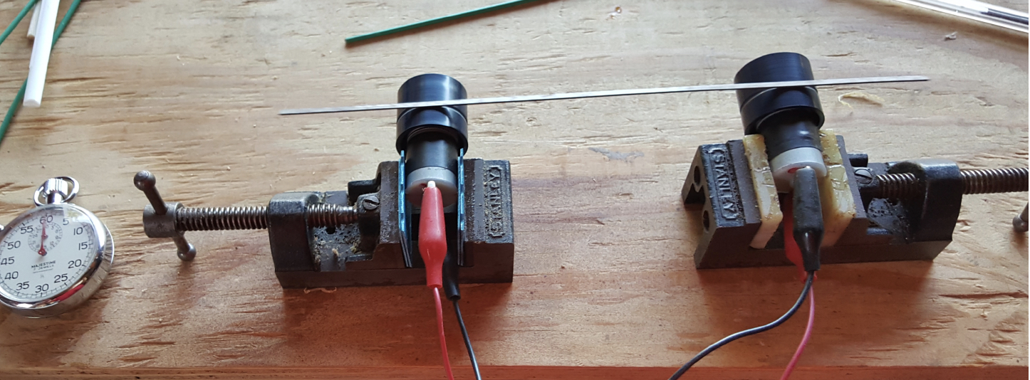
About the test fixture
Quantitative and qualitative proof of the formula
was accomplished using a test fixture constructed for this
specific purpose. It consists of two identical 3-Volt electric
motors, each with a hard plastic rotor about one inch in diameter.
The motors are wired to turn towards each other. The motors rotate
at about 100 RPM which seems to be an ideal rate for this
experiment.
Each motor is held in place using a small bench vise.
Motors are powered by an adjustable power supply, allowing tests
of oscillation rate with varying RPM. Testing proved oscillation
rate is independent of RPM.
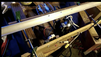
The bench vices sit on a track allowing adjustment of wheel base
from under three inches to more than meter. The track and vices
ensure the rotors are aligned and level.
Five different bars were used for testing. They are:
Large bar. 23 13/16 inches
long. Made of steel. Cut from a mattress frame. Rusty,
scratchy surface. Weighs about three ounces.
Short bar. Eleven inches long.
Same material as bar #1. These two bars were a single bar
cut in two pieces. Specifically selected to test whether
oscillation frequency is independent of mass as indicated by
the formula under test. Tests prove in fact that oscillation
rate is independent of mass. Wood stick. Eleven inches long, one eighth inch
in diameter. Very light. Smooth surfaces. Formerly a shish
kabab skewer.
Thin bar. Nine and seven eighths inches long. Light,
very thin, less than an eighth of an inch wide. Rusty
scratchy surface. Found on the ground at a construction
site. Weighs about a quarter of an ounce.
Plastic rod. Fifteen and thirteen sixteenth inches
long, three eights of an inch wide. Moderately light. Cut
from the long segment of a clothes hanger. Smooth surface.
Further details of fixture construction and links to video of the
device in operation are in appendix 1 of this document.
Qualitative proof
The video recording at this URL
https://www.youtube.com/watch?v=XMoAaabO78U shows demonstrations
varying the wheel base of with different bars. It is plainly
visible that extending the wheel base causes oscillation frequency
to decrease. Bars made of varying materials such as iron, plastic,
and wood were used; with lengths between 9 and 24 inches.
Measurements of wheel base and oscillation rate are detailed in
the following section on quantitative proofs.
Before measurements of wheel base and oscillation rate were taken,
a video was made recording some qualitative proof of the
expression under test. The video can be seen at:
https://www.youtube.com/watch?v=XMoAaabO78U
The video of these tests proved an expected result and showed some
anomalous and unexpected results.
As wheel base is extended, the oscillation rate clearly goes down.
This was proven using five different bars of varying material,
mass, dimension, and smoothness.
When the wheel base approaches length of the bar, in several cases
the oscillation rate went back up.
Oscillations are most varied with a very short wheel and the
heavier bars bounced around.
Oscillations are most consistent, smooth, and least varied when
the wheel base is about half the length of the bar. At this
position half the bar is between the rotors, and a quarter of the
length of the bar extends beyond the right and left rotors.
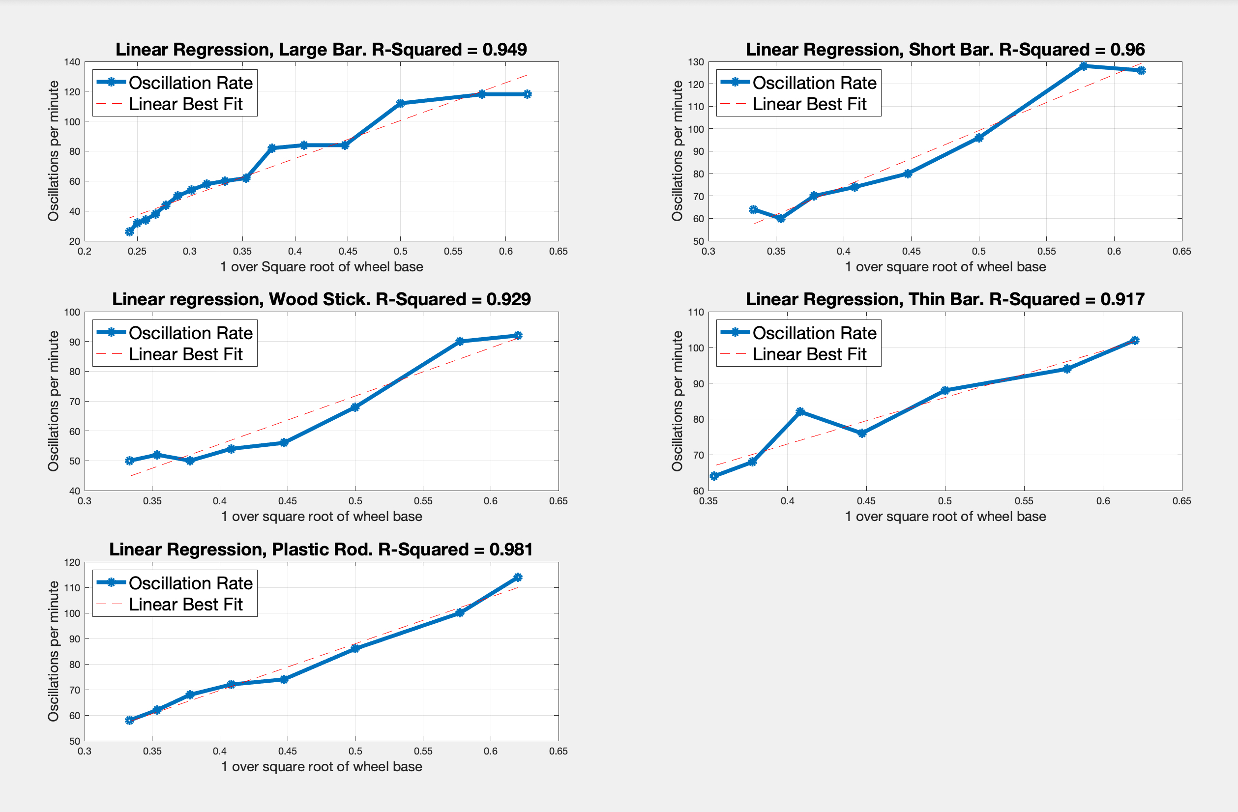
Quantitative proof
Test results prove that the relationship between oscillation rate
and square root of wheel base is inverse linear with very strong
R-Squared values from five different experiments.
Best fit analysis
The best fit analysis proves a linear inverse relationship between
oscillation rate and square root of wheel base.
The following five plots prove the equation is correct and
accurate. The graphs are each plot a magnitude one Matlab polyfit
of the test data, overlaid with a plot of oscillation rate against
the square root of wheel base. The R-Squared value for each pair
of vectors is also shown.
With one exception the R-Squared values are all over 90%. This is
high enough to cause suspicion among some statisticians who would
consider such a strong correlation too good to be true. This
information is a simple linear regression with a small number of
data points for each test. There are five independent tests so
veracity of the numbers is reasonable.
Readers of this white paper are free to download the test data. It
is in CSV format and accessible at this URL:
The Matlab code used to generate these reports and
graphs is also at the same web site, and can be downloaded from
this URL:
http://embeddedlinuxtestengineer.com/hb_SHM.m
Following are discussions of the best fit analysis, plotting
oscillations against wheel base, and an overview of the raw test
data.
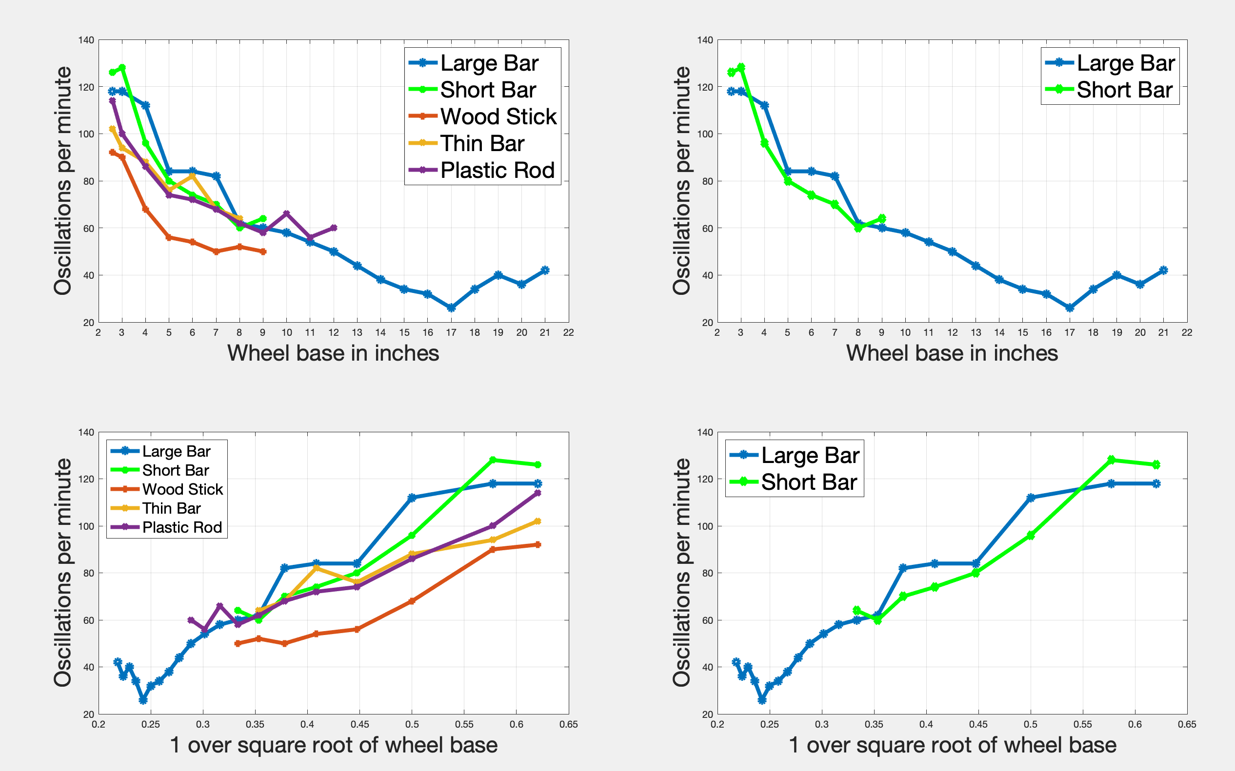
Plots of
oscillations and wheel base
The next set of four graphs is a rendition of all test results.
The first row shows oscillations vs wheel base. The second row
shows oscillations vs the square root of the wheel base. A visual
inspection of these shows there is an inverse relationship between
wheel base and oscillation rate.
The two graphs on the left are plots from tests recording
oscillations of five different bars:
Large bar. 23 13/16 inches
long. Made of steel. Cut from a mattress frame. Rusty, scratchy
surface.
Short bar. Eleven inches long.
Same material as bar #1. These two bars were a single bar cut in
two pieces. Selected specifically to test whether the
oscillation frequency is independent of mass as indicated by the
formula under test.
Wood stick. Eleven inches long,
one eighth of an inch in diameter. Very light. Smooth surfaces.
Formerly a shish kabab skewer
Thin bar. Nine and seven
eighths inches long. Light, very thin, less than an eighth of an
inch wide. Rusty scratchy surface. Found on the ground at a
construction site.
Plastic rod. Fifteen and
thirteen sixteenth inches long, three eighths of an inch wide.
Moderately light. Cut from the long edge of a clothes hanger.
Smooth surface.
The two graphs on the right plot test data from measurements of
two bars of identical material and different length. They were one
bar, taken from a mattress frame, then cut in two pieces.
Oscillation frequency according to the equation under test is
independent of mass. The expected result is that oscillation rate
of the two bars is the same and the graphs prove this is true.
Look at the test data
The following spreadsheet shows the raw data from test results.
The first column shows the wheel base of the fixture in inches.
The shortest possible wheel base is 2 9/16 inches. Oscillations
were then counted after expanding the wheel base in one inch
intervals.
Wheel
Base
in Inches
Large
Bar
23 13/16”
Short
Bar
11”
Wood
Stick
11”
Thin
Bar
9 7/8”
Plastic
Rod
15 3/16”
2
9/16”
59
63
46
51
57
3
59
64
45
47
50
4
56
48
34
44
43
5
42
40
28
38
37
6
42
37
27
41
36
7
41
35
25
34
34
8
31
30
26
32
31
9
30
32
25
falls
off
29
10
29
falls
off
falls
off
33
11
27
28
12
25
30
13
22
falls
off
14
19
15
17
16
16
17
13
18
17
19
20
20
18
21
21
22
falls
off
Rotors turn at 100 revolutions per minute. Oscillation rate does
not vary with RPM of the motors. Speed of the rotors causes the
bar to move farther back and forth, equivalent to increasing
amplitude, but this does not change the rate of oscillation.
The data first column shows oscillations in thirty seconds for the
“large” bar, with a wheel base ranging from 2 9/16 inches to 22
inches. Beyond that the 23 13/16 inches the bar falls off the
rollers. The numbers show an oscillation rate of 59 for the
shortest wheel base, 21 for the longest wheel base, and minimum of
13 at seventeen inches.
Oscillation rate decreases as the wheel base is expanded up to
seventeen inches. Beyond that point oscillation rate increases.
This anomaly has been seen in tests with two different bars. The
formula under test does not account for this. So far a plausible
explanation has not been found.
In order to statistically account for this anomaly and to be
consistent with good scientific method, these four anomalous
statistics were simply dropped from the goodness of fit analysis.
:) With these four figures included in the R-Squared analysis the
R-Squared value would be 0.894 rather than 0.973.
The second data column shows oscillations of the ‘short’ metal
bar, made of the same material as the ‘long’ bar, and is tested
with the intention of proving oscillation frequency is independent
of mass. This bar is eleven inches long. At the shortest wheel
base it oscillates 63 times in half a minute, and as the wheel
base is extended to ten inches the oscillation rate declines.
The third data column shows oscillations of an eleven inch wood
stick. It is very light with a relatively smooth surface. The
oscillation rate declines from a maximum of 47 at the shortest
wheel base, and declines to a rate of about 25 when the wheel base
is seven inches. From seven to ten inches in wheel base the
oscillation rate does not change.
The fourth data column shows oscillations of a very thin metal bar
that has a lot of rust on it. Oscillations decrease in frequency
as the wheel base is extended.
The fifth data column shows oscillations of a thick light rod of
plastic that is 15 3/16 inches long. These measurements exhibit a
pattern similar to that of the large bar. With the shortest wheel
base oscillations are rapid. As the wheel base is extended,
oscillations slow down until a wheel base of ten inches is
reached, and then the rate goes up. This result was seen in some
tests. These final three numbers were removed from the best fit
analysis, but R-Squared values with and without the anomalies are
presented. If these three numbers were included in the R-Squared
computation, the R-Squared value would be 0.838 instead of 0.926.
Margin of error
The estimated margin of error in oscillation counts is three to
five percent above and below the numbers shown, explained as
follows:
All oscillation figures shown are the average of five
measurements. Actual numbers varied by up to five percent above
and below that mean.
It is inherently difficult to count oscillations by inspection and
this may contribute to the margin of error.
Oscillation of all rods tested was inconsistent and uneven, and
for this reason an average of five measurements is recorded in
this paper.
Oscillation of the ‘long’ and ‘short’ bars at two shortest wheel
base measurements was especially erratic.
The estimated margin of error in wheel base length is one
sixteenth of an inch.
Summary and conclusions
Oscillation frequency of a horizontal bar on two
rollers turning towards each other is:
⍵ = √ (2 * uK * g / L)
This formula is computed using a summation of horizontal forces,
vertical forces, and torques; followed by some creative algebra.
The formula is correct, accurate, and empirically provable.
Visual inspections of experiments indicate this formula is
correct.
Empirical tests prove the formula is correct. This is best shown
in the five graphs of best fit analysis. All R-Squared values are
above 0.835 and most are above .926, indicating a very strong
correlation.
Oscillation rate is independent of mass of the bar and speed of
the rotors.
The formula also exhibits a direct square root relationship
between the coefficient of kinetic friction and oscillation
frequency. A suitable method of testing this has not been
developed.
Analogues to oscillation of a simple pendulum
There are four analogues to oscillation of a simple pendulum in
this experiment.
Oscillation rate of a simple pendulum is the square root of
acceleration due to gravity divided by pendulum length. This
differs from oscillation rate of the horizontal bar by a pair of
constants.
Oscillation of both systems is independent of mass. This was
proven for the horizontal bars in this experiment.
Limits of small angle approximation seem to apply:
Within the limits of small angle approximation, the initial angle
of a simple pendulum has no effect on oscillation rate. This seems
to be analogous to adjusting RPM of the rotors. A higher RPM
produces greater amplitude and lateral velocity of the bar, but
does not change oscillation rate.
If the angle of a simple pendulum exceeds that of a ‘small angle’
then the formula for oscillation rate no longer applies. This
seems to be analogous to extending wheel base to nearly the length
of the bar.
Testing the coefficient of kinetic friction
Tests varying the wheel base were successfully conducted, but
experiments to prove the effect of varying the coefficient of
kinetic friction were inconclusive. Two bars, with a very smooth
surface and presumably a low value for coefficient of kinetic
friction, being the plastic rod and wood stick, did not display
significant difference in oscillation rate of the three metal bars
with rough, rusted, and scratchy surfaces.
Appendix 1 -
Fixture construction
This section is written in response to various requests from
students, teachers, and tutors interested in making one of these
oscillating whirly-gigs. From a visual inspection of the most
recent machine it is apparent this is not a painfully difficult
project, and this section of the document is largely intended to
point out caveats and pitfalls from prior experience so that
interested people can make one without wasting time repeating some
of my mistakes.
Please note there is a separate video covering this same topic of
how to make the fixture. It can be seen at:
https://youtu.be/o_54gWHb6BE
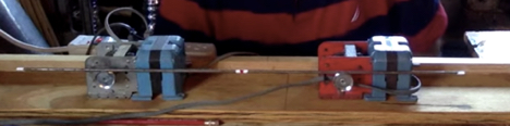
Fixture #5, seen in all demonstrations, and in the picture below,
is made using a pair of three volt electric motors that were taken
from a Zip Notes dispenser. The machines cost about $15.00 each
and can be ordered on line from zipnotes.com
The rotors came with the electric motor
These motors seemed to make for the perfect test fixture. At 100
RMP the rotation rate was just right. The rotors are made of
plastic and produce the right amount of friction to make a visible
consistent oscillation. Other test devices, with very smooth rotor
surface or faster motor, were less successful.
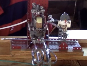
The motors are held in position using identical small Stanley
bench vises, available at specialty hardware stores for about
$25.00 each. The vises sit on a track made of plywood allowing for
precise alignment.
The motors are powered by an adjustable power supply with a range
from 1.5 to 12 volts. While the motors are rated at 3 volts,
nearly all tests are done with 1.5 volts. Increasing the voltage
increases increases lateral speed, amplitude, and has no effect on
oscillation rate. At very high RPM test bars do not seem to
oscillate consistently. Supplying more than 3 volts to the motors
for any length of time caused them to burn out.
The advantages of this system are:
Near perfect RPM (100) for test
purposes
Excellent level of friction on the
rotors
Small groove on the rotors helps keep
bars in place
The wheel base is adjustable to any
length, limited only by the fragile motors’ ability to
support bars weighing more than about three ounces
The only disadvantages of this system are:
The motors will wear out and require
replacement after about 20 hours of use
The motors are weak and require light
bars. Three ounces is about the heaviest bar that will
still allow a consistent sustained oscillation.
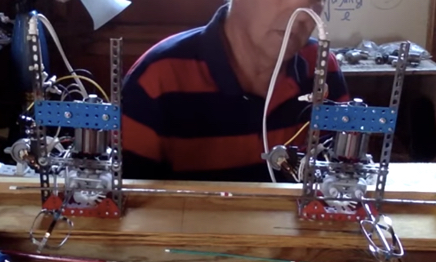
Fixture #4, seen in the video and following picture, was made with
a pair of Erector Set electric motors.
While the geared motors supported a suitable RPM and produced
consistent oscillations, the disadvantages are:
Excessive motor vibration
Motors overheat quickly
Bars greater than a quarter inch in
diameter do not fit
Accurate alignment and wheel base
adjustment, without a complex retaining fixture, is
difficult
The remaining three fixtures, all made using electric motors from
a cake mixer, had the same disadvantages, which were:
Very smooth rotor surface did not
produce a consistent observable oscillation
Even at the slowest speed the RPM was
much too high
Excessive motor vibration
Fixture #3 is a pair of identical mixer motors mounted in separate
frames allowing easy and simple adjustment of the wheel base. The
motors are mounted in frames made from an erector set. The only
advantage of this design is an adjustable wheel base, but the
rotors turn much too fast and the hard metal surface of the rotors
produced very little friction
Fixture #2 is a single mounted mixer motor, with all the
disadvantages of fixture #3, plus a narrow and fixed wheel base.
Fixture #1 is a single mixer motor, mounted in a wood frame with
an eighteen inch fixed wheel base. The rotors are turned using
rubber bands as a belt. Like all the fixtures using a mixer motor,
the RPM is too high and the rotor surfaces are too smooth.
Cautionary notes re:
fixture construction and sourcing parts
For those attempting to build one of these fixtures
I would strongly advise caution when raiding your wife’s kitchen,
vanity, or sewing room, for parts. The wood sticks were originally
shish-kebab skewers and for some reason my wife was unhappy when I
took them all and cut them up. She was especially unhappy when I
began dissecting some of her cake mixers, and it did not help
things when I bought two more for test fixtures, at prices
significantly above the price of ones she originally had. Never
mind that she still has at least two of them. Then for some reason
she also became annoyed when I started taking all her white and
red nail polish to mark the ends and center of gravity of all the
bars used for testing. Nor did it help when I took a few large and
apparently expensive knitting needles for testing as a bar. The
dents and scratches just weren’t that bad. Then I took apart her
favorite ZipNotes machine that had been on her desk. I just did
not know she really used it. I thought she kept asking for paper
refills for her friends.
For a while now I have been living in the garage and not because I
want to. I just hope this all blows over before cold weather sets
in.
Just giving you a heads up.
Appendix #2 -
Reference Information
This section is written for people who have asked where this
problem came from and where to look for more information. It can
be found in several text books, white papers, and recorded physics
lectures from U.C. Berkeley.
The problem is illustrated on pages 377 and 378 in “Fundamentals
of Physics” by Haliday, Resnick, and Walker, fifth edition. While
there are many editions of this very well known physics text, the
problem is found only in the fifth edition.
Copies of the pages from Haliday and Resnick are on Chegg, along
with a vacuous regurgitation of the book’s solution. It is worth
looking at this solution because the approach is different, using
a different axis of rotation for computing torques, and using
torques from gravity to help solve the problem.
I first heard of this problem from Dr. Achilles D. Speliotopoulos
when he taught Physics 250 at Canada College in Redwood City, CA,
during the fall 2015 semester. Dr. Speliotopoulos is a physics
professor at U.C. Berkeley and occasionally moonlights at a local
community college, which is how I had the privilege and pleasure
of learning this. The problem caught my attention right away
because it seemed to appear that a fixture demonstrating it could
be easily built. At least I thought it would be easy…
Audio recordings of Dr. Speloptopoulos’ physics lectures at
Berkeley can be heard at:
The lecture dated 11/26/2014 contains his more eloquent
description and solution. The preceding lecture, on 11/24/2014, is
also worth listening to, with explanations of the equation of
motion and other interesting problems with oscillation frequency.
The fixture Dr. Speliotopoulos uses to demonstrate the problem can
be seen at:
http://berkeleyphysicsdemos.net/node/47
There is a short white paper about this problem, found at:
https://arxiv.org/pdf/0907.3378.pdf
While I found the paper less than illuminating it contains
reference to another physics text that reportedly describes the
problem.
An explanation of the problem, and an alternate solution, is
presented by Physics Galaxy, at:
https://www.youtube.com/watch?v=Ml0TFKzWcOU
Appendix #3 - Hyperlinks to test data, Matlab code, and videos
Soft-copy of the test data seen on page 19 can be
downloaded from:
A video by this author showing how the expression for oscillation
rate is computed can be seen at:
A video by this author citing sources and references can be seen
at:
A video by this author presenting the qualitative and quantitative
proof of the expression can be seen at:
A video by this author about how to construct a
suitable test fixture to demonstrate this problem can be seen at:
Contact
information
If you have comments or questions regarding this paper or any
aspect of the proof, fixture construction, or anything else please
feel free to send a note and I will write back.
Many thanks,
-Dave Ge
Redwood City, CA
June, 2019
daveg@embeddedlinuxtestengineer.com